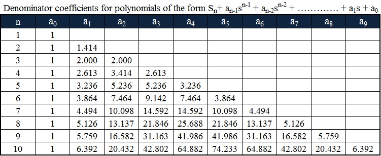
Butterworth Filter Transfer Function. However any dc gain can be obtained by simply multiplying 1 22 by the correct constant. The following bullet points will help you to unpack the information contained in this diagram.

This particular filter has four poles. The butterworth filter having a given transfer function can be realised using a cauer 1 form. Butterworth filtering transfer function a1 continuous time low pass butterworth transfer function in order to obtain the values for the components in a filter using the circuits transfer function a prototype transfer function must be used.
We would like to obtain a new filter h s with a dc gain of 10 and a half power frequency ω h p 100 rads.
The product of every pair of complex conjugate poles can be expressed using formulas 35 for butterworth poles. Butterworth filtering transfer function a1 continuous time low pass butterworth transfer function in order to obtain the values for the components in a filter using the circuits transfer function a prototype transfer function must be used. 4 the stopbandfrequency s. The above equation can.